
Eğitimler
Calibration
Bu örnek, sensör girişini kalibre etmek için bir teknik göstermektedir. Kart, başlatma sırasında sensör okumalarını beş saniye boyunca alır ve aldığı en yüksek ve en düşük değerleri izler. Çizim yürütmesinin ilk beş saniyesindeki bu sensör okumaları, döngü sırasında alınan okumalar için beklenen minimum ve maksimum değerleri tanımlar.
Gerekli Donanım
- Arduino veya Genuino kartı
- LED
- analog sensör (bir fotodirenç yapacak)
- 10k ohm direnç
- 220 ohm direnç
- bağlantı telleri
- breadboard
Devre
Analog giriş 2 üzerindeki analog sensör (örn. Potansiyometre, ışık sensörü) Dijital pim üzerindeki LED 9.
büyütmek için resme tıklayın
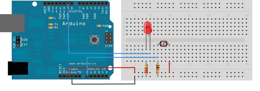
220 phm akım sınırlama direnci seri olarak dijital pim 9'a bir LED bağlayın. 5V'a ve daha sonra toprağa 10K ohm direnç ile analog pim 0'a bir fotodirenç bağlayın.
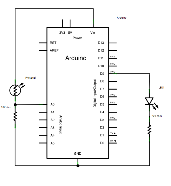
Şematik
büyütmek için resme tıklayın
Kod
Kurulumdan önce, minimum ve maksimum başlangıç değerlerini şu şekilde ayarlarsınız:
int sensorMin = 1023; // minimum sensor value int sensorMax = 0; // maximum sensor value
Bunlar geriye doğru görünebilir. Başlangıçta, minimum değeri ayarlarsınız ve bundan daha düşük herhangi bir şey için okursunuz, bunu yeni minimum değer olarak kaydedersiniz. Aynı şekilde, maksimum düşük değerini ayarlar ve yeni maksimumdan daha yüksek bir şey için okursunuz, şöyle:
// calibrate during the first five seconds while (millis() < 5000) { sensorValue = analogRead(sensorPin); // record the maximum sensor value if (sensorValue > sensorMax) { sensorMax = sensorValue; } // record the minimum sensor value if (sensorValue < sensorMin) { sensorMin = sensorValue; } }
Bu şekilde, aldığınız diğer okumalar bu minimum ve maksimum arasındaki aralığa şu şekilde eşlenebilir:
// apply the calibration to the sensor reading sensorValue = map(sensorValue, sensorMin, sensorMax, 0, 255);
İşte tüm program:
/*
  Calibration

  Demonstrates one technique for calibrating sensor input. The sensor readings
  during the first five seconds of the sketch execution define the minimum and
  maximum of expected values attached to the sensor pin.

  The sensor minimum and maximum initial values may seem backwards. Initially,
  you set the minimum high and listen for anything lower, saving it as the new
  minimum. Likewise, you set the maximum low and listen for anything higher as
  the new maximum.

  The circuit:
  - analog sensor (potentiometer will do) attached to analog input 0
  - LED attached from digital pin 9 to ground

  created 29 Oct 2008
  by David A Mellis
  modified 30 Aug 2011
  by Tom Igoe

  This example code is in the public domain.

  http://www.arduino.cc/en/Tutorial/Calibration
*/

// These constants won't change:
const int sensorPin = A0;    // pin that the sensor is attached to
const int ledPin = 9;        // pin that the LED is attached to

// variables:
int sensorValue = 0;         // the sensor value
int sensorMin = 1023;        // minimum sensor value
int sensorMax = 0;           // maximum sensor value


void setup() {
  // turn on LED to signal the start of the calibration period:
  pinMode(13, OUTPUT);
  digitalWrite(13, HIGH);

  // calibrate during the first five seconds
  while (millis() < 5000) {
    sensorValue = analogRead(sensorPin);

    // record the maximum sensor value
    if (sensorValue > sensorMax) {
      sensorMax = sensorValue;
    }

    // record the minimum sensor value
    if (sensorValue < sensorMin) {
      sensorMin = sensorValue;
    }
  }

  // signal the end of the calibration period
  digitalWrite(13, LOW);
}

void loop() {
  // read the sensor:
  sensorValue = analogRead(sensorPin);

  // apply the calibration to the sensor reading
  sensorValue = map(sensorValue, sensorMin, sensorMax, 0, 255);

  // in case the sensor value is outside the range seen during calibration
  sensorValue = constrain(sensorValue, 0, 255);

  // fade the LED using the calibrated value:
  analogWrite(ledPin, sensorValue);
}
See Also
- while()
- millis()
- constrain()
- map()
- If
- AnalogInOutSerial- Bir analog giriş pinini okuyun, sonucu eşleyin ve ardından bir LED'i kısmak veya aydınlatmak için bu verileri kullanın.
- AnalogInput- Bir LED'in yanıp sönmesini kontrol etmek için bir potansiyometre kullanın.
- AnalogWriteMega- Arduino veya Genuino Mega kartı kullanarak 12 LED'i birer birer söner ve söndürür.
- Fading- Bir LED'in solması için bir analog çıkış (PWM pin) kullanın.
- Smoothing- Bir analog girişin çoklu okumalarını düzgünleştirin.